Final Report on 2010-2015 Green infrastructure TCEQ/USEPA 319h project
DALLAS URBAN CENTER STORMWATER BMPS
Low Impact Development Project at the Texas A&M AgriLife Research and Extension Center – Dallas
Stormwater Project: What is Green Infrastructure for Stormwater and How Well does it work?
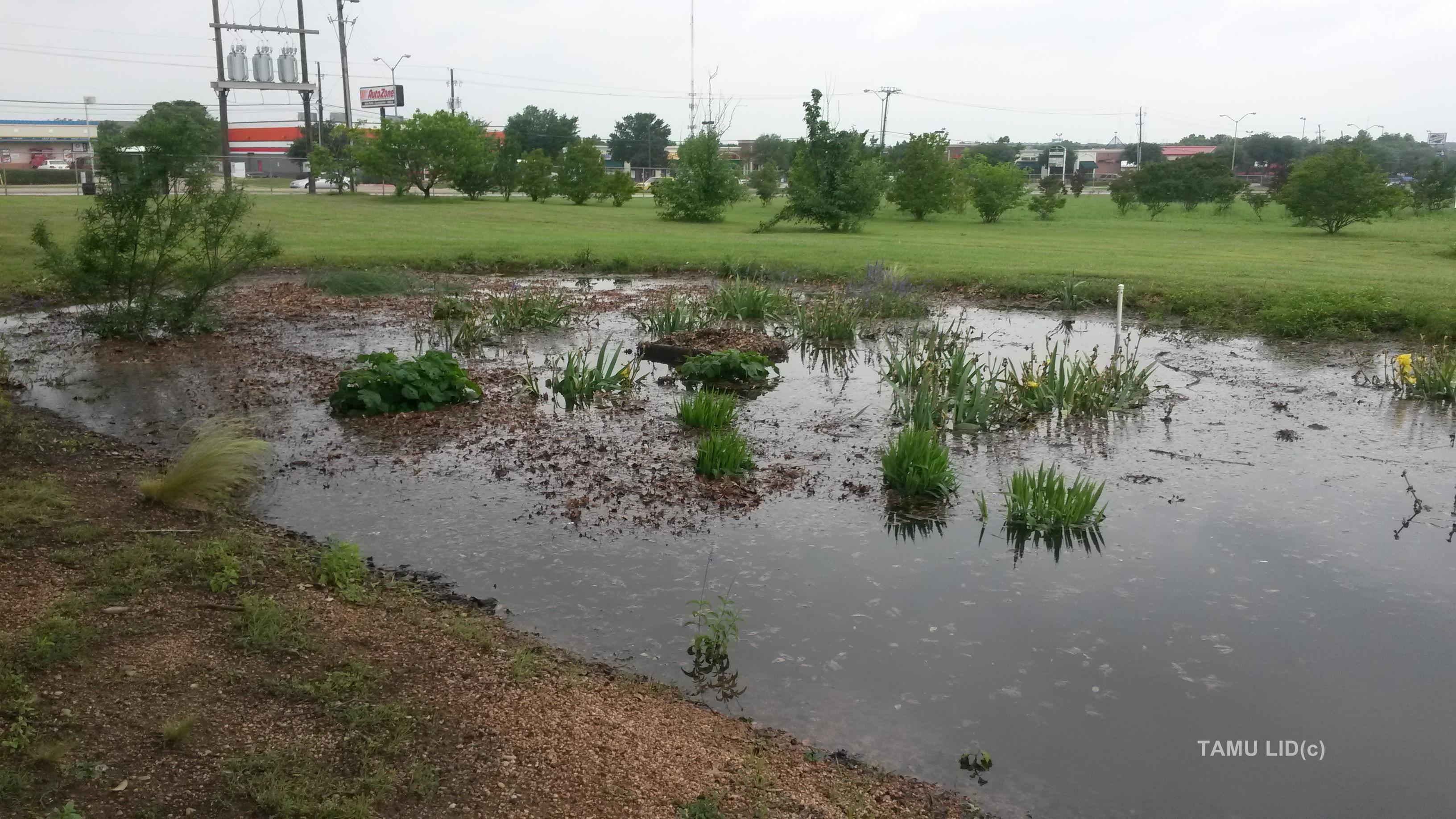
Fig.1 Stormwater at the Texas A&M AgriLife Dallas Urban Center. (Click to Enlarge all Photos)
In Texas storm water comes down fast and can easily flood.Green infrastructure for stormwater or low impact development (LID) refers to practices that manage stormwater in an urbanized setting in a way that minimizes impact to the environment, while increasing cost effectiveness and sustainability. Under this approach, best management practices such as bio-retention, green roofs, rainwater harvesting, and permeable pavements, are incorporated into new or existing infrastructure. These help reduce the volume and pollutant load carried by surface storm water runoff into rivers and lakes.
Background and Rationale
Nonpoint Source (NPS) stormwater runoff is the leading cause of water quality impairment in the United States (USEPA, 2005). Recent rapid urbanization and population growth have exacerbated this problem. Traditional urban development increases the imperviousness of land. This in turn results in increased total runoff volume, increased peak runoff flow, decreased time to concentration, and deteriorated water quality (Dietz et al., 2007). Urban runoff contaminants typically include sediments, oil, grease, pesticides and nutrients from yards, roads, and parking lots. In the Upper Trinity River watershed, legacy pollutants (chemicals no longer in active use) including chlordane and PCBs continue to find their way into the river and reservoirs as part of the sediment load, where they continue to accumulate in fish tissue and contribute to public health concerns.
While recent studies have evaluated the effectiveness of LID practices in various regions in the United States, there is still a great need to evaluate these practices in the field and to collect quantitative data on the performance of LID practices, especially in the Southern part of the United States. There is also very little data on the potential impact of the adoption of LID practices at a watershed level, or in North Texas.
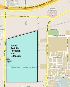
Fig.2 Texas A&M AgriLife Dallas Urban Center
The Project
The goal of this project is to improve the quality and reduce the total and peak flows of stormwater from a site typical of commercial development in the Upper Trinity and White Rock Lake watersheds. The project aims to design, construct and evaluate several LID practices at the Texas AgriLife Research and Extension Center in Dallas. These Best Management Practices (BMPs) will provide examples of how LID can be integrated in new buildings and developments or retrofitted to existing developments that aim at reducing sediments (and sediment bound pesticides), and nutrients loadings into urban runoff. The five LID BMPs targeted in this study are permeable pavements, bio-retention area, rainwater harvesting, green roofs, and detention ponds (Figure 3). These technologies will be assessed for their ability to treat the legacy pollutant chlordane that is a concern in the White Rock and Upper Trinity River watersheds. Nitrogen, phosphorus, chlordane and total suspended solids will be analyzed. In the case of the green roofs, rainwater harvesting and permeable pavement, a controlled experimental setup will be constructed to collect performance data.
Funding for the project is provided by the CWA 319 (h) NPS grant programs Prepared in cooperation with the Texas Commission on Environmental Quality (TCEQ) and the U.S. Environmental Protection Agency (USEPA) with match provided by Texas AgriLife Research. Data collected as a result of the project will be used to demonstrate the effectiveness of construction of the LID BMPs, in terms of reduction of pollutant loads mentioned above. This demonstration will be further used to promote knowledge, awareness and implementation of the demonstrated BMPs among individuals, businesses and government entities.

Fig.3 Texas A&M AgriLife Dallas Urban Center
Rain Gardens
Rain gardens or bioretention areas are designed to capture stormwater runoff, filter it through a special media and allow it to infiltrate, evapotranspire or flow out. Rain gardens consist of excavated basins equipped with a perforated pipe underdrain. The underdrain is covered by a special soil- compost media in which specific vegetation is planted.
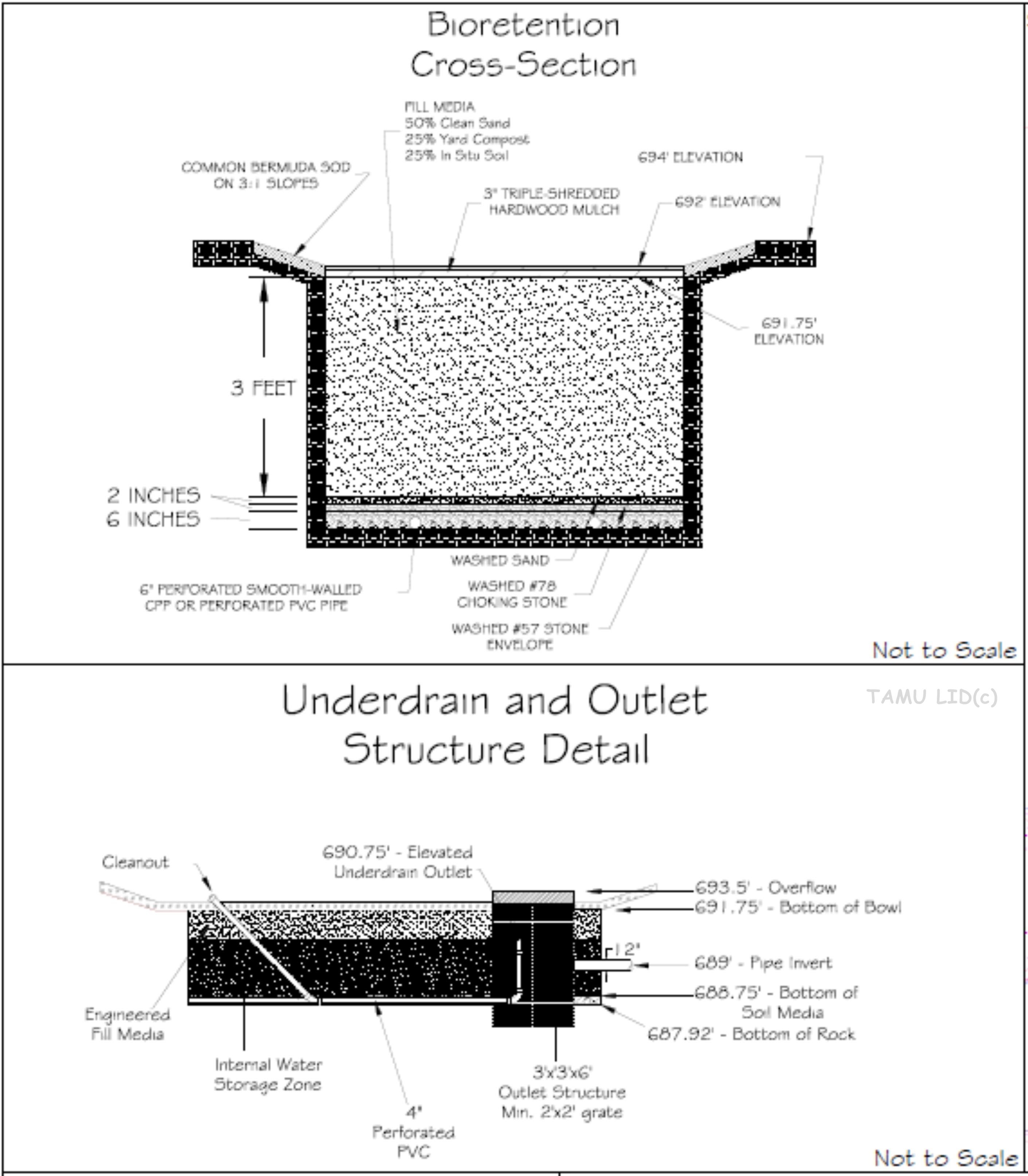
Fig. 3 Blueprint of the Bioretention area
The rain garden has curb openings with a 1-foot H-flume that collects runoff from the parking lots and building at the Texas A&M AgriLife Dallas Urban Center for automatic ISCO sampling and flow measurement. Additionally, the drainage layer of the rain garden houses perforated pipes that assist in soil infiltration. A flow measurement device will measure the combined overflow and perforated pipe flows. A pressure transducer is installed within a well point to measure soil water storage. Plants selected are based on optimal performance of the rain garden, including treatment of the storm water. Designs for the Rain garden/Bio-retention area were designed and created for the Texas AgriLife Research and Extension Center, Dallas.
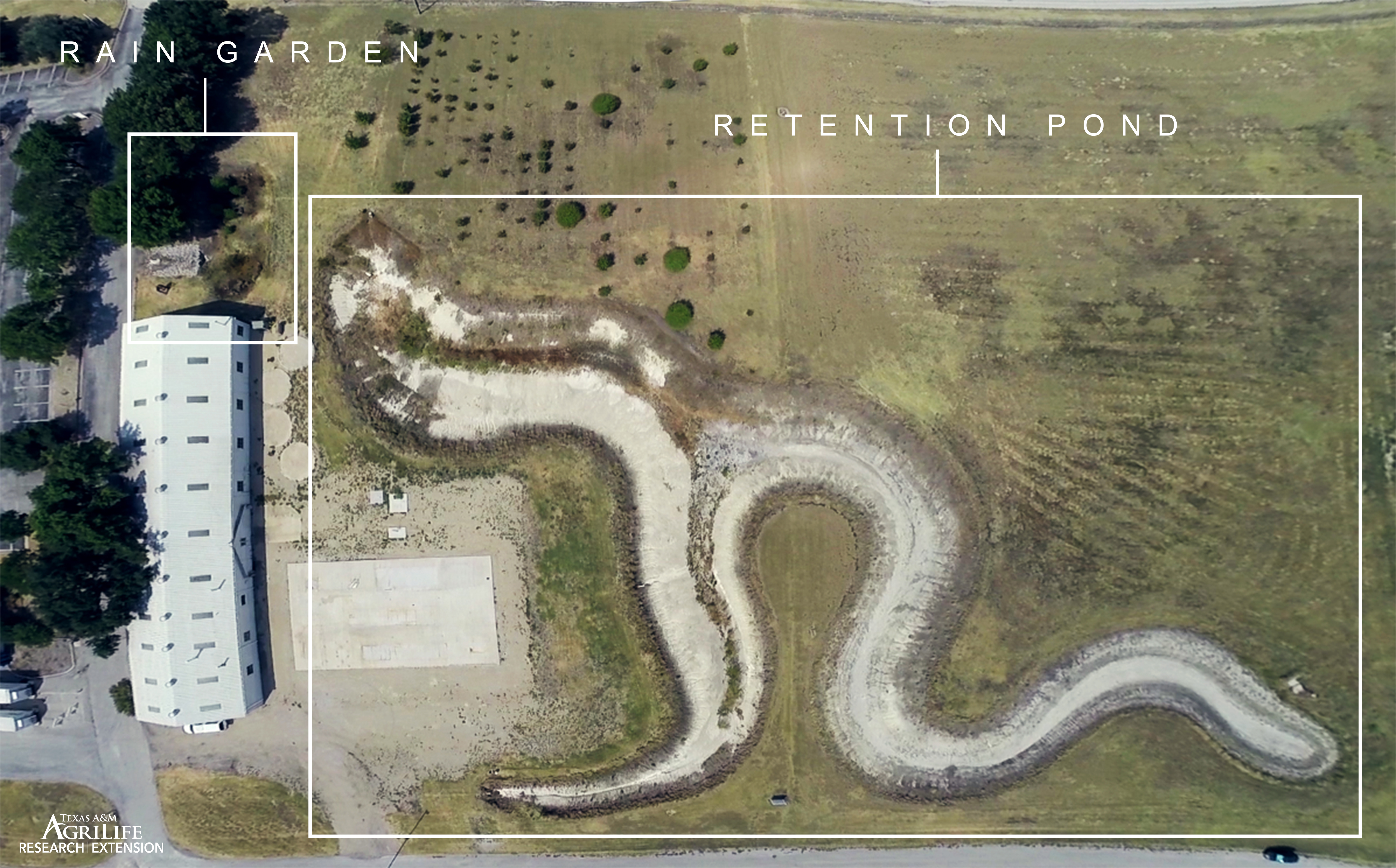
Fig. 4 Aerial photo of the combined bioretention and detention areas
Overall, the monitoring data quantifies total water inflow (runoff), outflow (runoff and infiltration), soil water storage, and pollutant balances. Our results can be viewed here. The rain garden will be maintained beyond the scope of this project as a demonstration for the public.
Retention/Detention Ponds
Detention Ponds are basins that hold stormwater runoff and release it slowly to a nearby water course or water body. A detention pond can be dry, (i.e. hold water only during and right after storms) or wet (i.e. have a permanent pool of water). Dry detention ponds have outlets (usually a culvert) located at the same level as the bottom of the pond. The culvert’s size limits the outflow thus reduces the flow rate from large storms. Wet detention ponds have a permanent pool of water. By placing the outflow at an elevated location, a wet detention pond stores the water from the previous storm, to release it only during the next storm. This allows for the sediments in the stormwater to settle, and biological and chemical reactions with vegetated benches can then improve the quality of the water. Wet detention ponds are either constructed on low infiltration soils or sealed with a liner at the bottom. Both these designs reduce peak flow rates while the wet detention pond has additional water quality benefits. Neither reduces the total volume of stormwater, an essential feature of LID structures.
In certain soil and weather conditions, detention ponds can be modified to act similarly as LID structures where it would be designed to retain a portion of the runoff, in addition to the water quality benefits and the peak flow reduction.
Under this project, a modified detention pond was designed to retain 1.5 inches of runoff and will be measured for inflow/outflow and its respective water quality. The pond will be designed to resemble a meandering river with associated vegetation to reduce erosion as well as act as filter strips, to serve as a demonstration tool for stream restoration. The width to length ratio will also be taken into consideration to maximize sediment retention and nutrient intake. Our results can be viewed here.
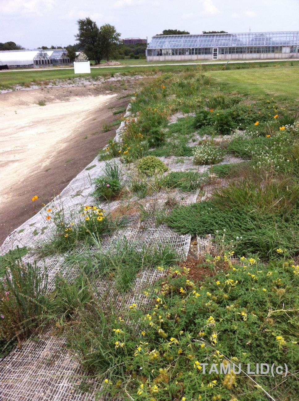
Fig. 5 Detention pond filter strip with native plants
Rainwater Harvesting
Rainwater harvesting systems capture runoff from rooftops and store it in large cisterns and containers for later use.
The rainwater harvesting BMP involves a demonstration component as well as a controlled experiment component. The demonstration component (Fig. 6), already in place, will monitor several rainwater tanks installed on Center buildings. Four cisterns (300, 500, 1500, and 2500 gallon tanks) will record water levels and flow and demonstrate usage of stored rainwater for a drip irrigation system installed on campus.

Fig. 6 RWH Demonstrations at the Dallas Urban Center. (Click to Enlarge all Photos)
The controlled experiment consists of four roof shelters with a turf lawn beside each. Three shelters each have a gutter with leaf guard and a downspout draining to three connected rainwater harvesting barrels. The lawns connected to these three shelters will be irrigated with the harvested rainwater. One control plot has a downspout draining directly to the lawn, to simulate a lawn that is not equipped with any rainwater harvesting system. The lawn connected to this control plot will be irrigated using city water, to demonstrate the water savings from rainwater harvesting systems. Our results can be viewed here.

Fig. 7 RWH Experimental Plots at the Dallas Urban Center
Permeable Pavement
Permeable, or pervious, pavements allow water to pass through them to an underground storage area to help water infiltrate the soil. This is unlike traditional impervious pavements that cause stormwater runoff. An underdrain system of perforated pipes allow water to flow out in the event of a flood event.
Four different kinds of permeable pavements were constructed and evaluated under this project. These include: grass pavers, permeable interlocking block pavers (PIPC), porous concrete, and gravel pavers. A constructed and functional parking lot to serve the Texas AgriLife Center at Dallas will incorporate each of these pavements as well as a section of impervious concrete to serve as control.
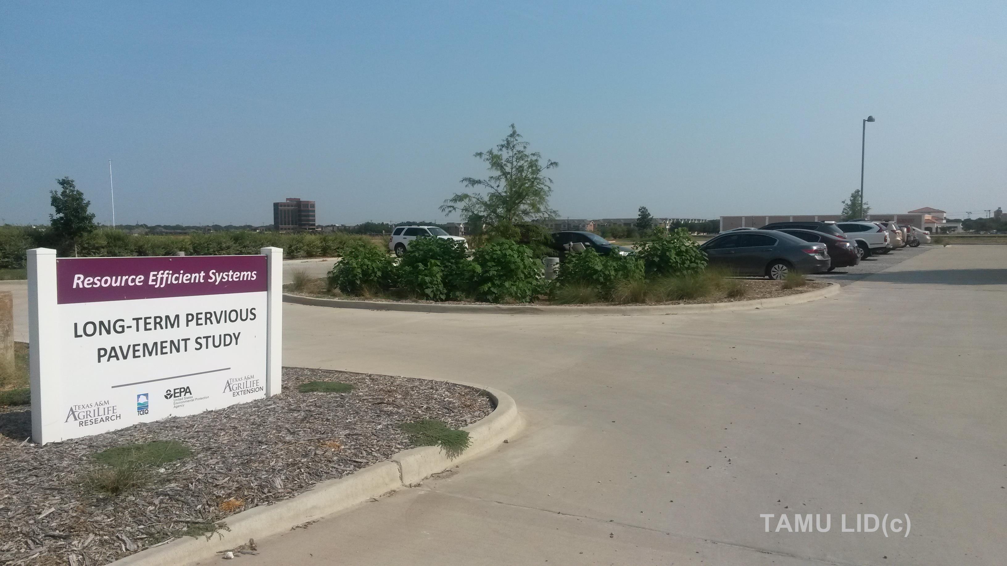
Fig. 8 Long Term Pervious Pavement Study, Comparing traditional concrete with four types of LID options.
Five parking stalls of each pavement type (five total) make up this experimental parking lot. The parking stalls include sub-grade and sub-base designs, and perforated pipes as recommended by the literature. The designs also include provisions to hydrologically separate the varied parking types from each other.
The experimental parking stalls are part of a larger parking lot intended to hold approximately 110 stalls. The remaining stalls are constructed of pervious concrete. With the data collected from the experimental stalls, a representation of runoff and pollutant reduction can be estimated for the total parking lot. Our results can be viewed here.
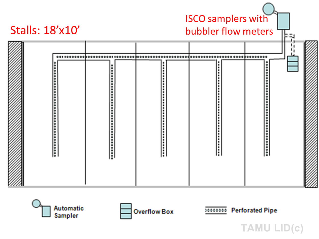
Fig. 9 Blueprint for each Permeable Pavement Type
Green Roofs
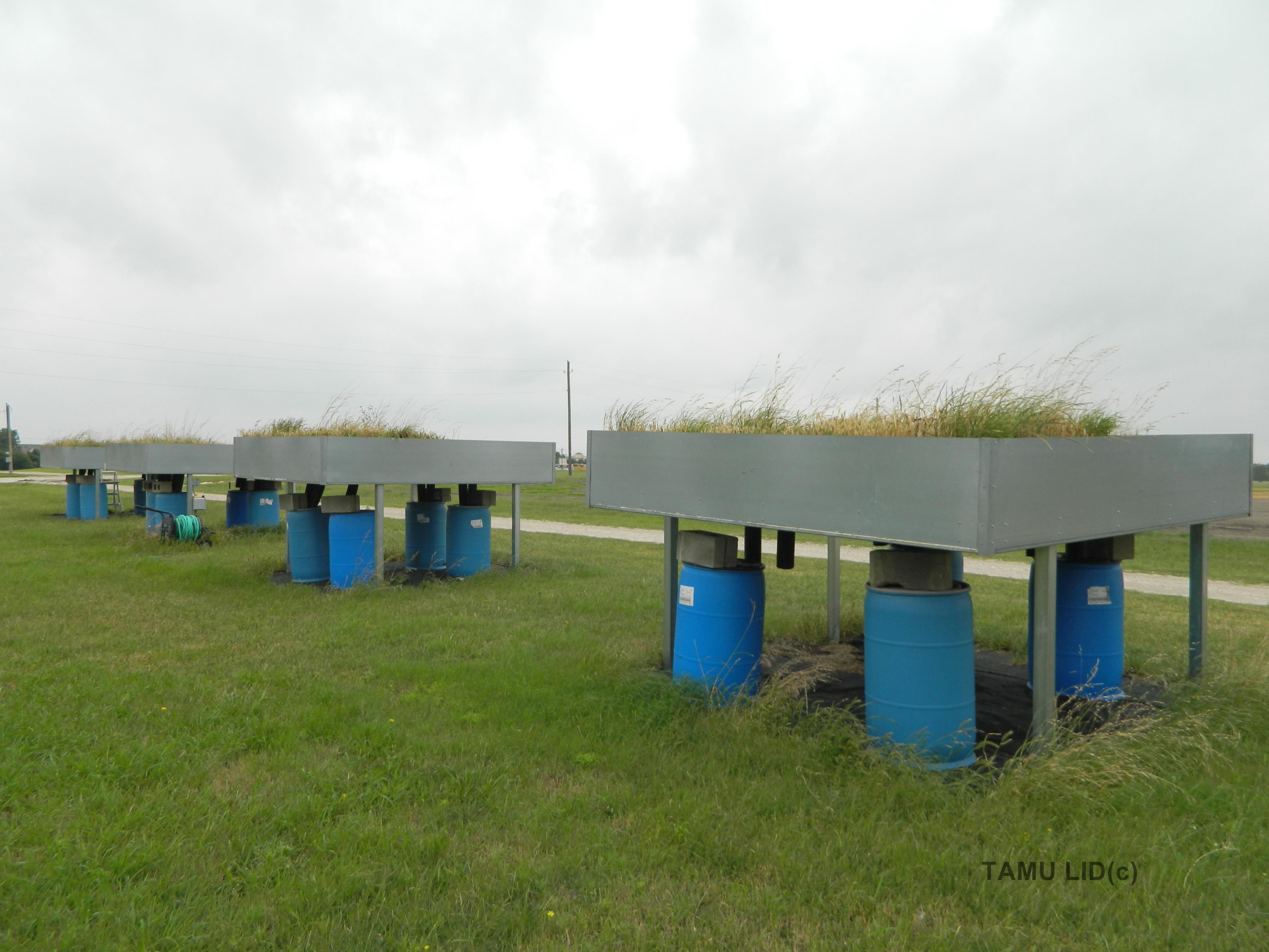
Fig. 10 Experimental Green Roofs at the AgriLife Dallas Center. (Click photos to enlarge)
Green roofs consist of a modified base covered in filter strips, water storage, soil media and vegetation instead of traditional roofing material such as asphalt and tiles.
The controlled experiment will feature four roof shelters representative of a residential roof with varying green roof designs. Each roof will be divided into four sections to compare four types of growing media that will include different layers of soil, drainage, insulation and roofing membranes. Plants will be selected to withstand minimal maintenance. These green roofs also consist of the following components:
- Plants selected for their ability to withstand drought and self -regenerate.
- Engineered lightweight growing medium that has suitable pH range, nutrients, and porosity for plant growth.
- Drainage layer that retains water in profiled troughs, and drains away excess water through channels between troughs.
- Insulation layer that resists moisture and situated above roof membrane and root barrier
- Root barrier that prevents roots from affecting the roof membrane.
- Testing of the roofing membrane made of Hydrotech’s Monolithic Membrane®.
- Structural support that is designed to support the weight of the green roof.

Fig. 11 The four types of experimental Green Roofs tested.
All green roofs are monitored for rainfall, soil water storage, and runoff on a continuous basis. Water samples were collected from the runoff to demonstrate the effectiveness of green roofs in removing pollutants as well as water quantity reductions. Our results can be viewed here.